Esprimo P910 dual-PSU approach evaluation
Introduction
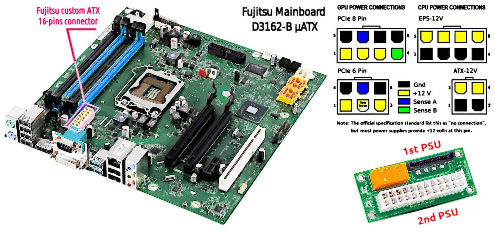
This paper is going to present the way in which I decided to provide that system with a secondary 350W power supply unit in order to sustain the K80 consumption and aid venting for properly cooling the GPU card. Among the main issues one in particular was related to the Fujitsu Esprimo P910 which like many others slim-tower with Zero-Watt technology includes a customised power supply unit which has a single connection to the mainboard with a 16-pin connector and cannot be replaced with any standard ATX PSU also because its own way of being fixed to the case. Well - cannot be replaced - in the sense of a spare part because mechanical changes to the case in order to fit a standard PSU supply as well as providing a cable for adapting the standard 20/24-pins ATX connector to the motherboard 16-pin one, is always possible. However, as you can imagine some mods' outcomes are less predictable than assembling commercially available parts. In particular, when 220V power supply is involved.The DVD bay
A place in which a secondary PSU can be installed in the Esprimo P910 case is the DVD reader bay, and there are two. I am not going to use that device, hence both are available. Despite this the two bays are separated with a frame that also provides a substantial distancing to the front side unless the PSU would have a size comparable with a DVD reader. After a search on the Internet, I have found that an ATX PSU built for PoS devices which has a standard size of 1U = 1 rack Unit can fit into that area replacing the DVD reader.Powering up
Once decided where to place the 2nd PSU there are two more task to face: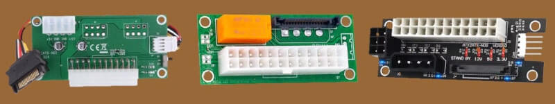
Update 2025-02-10
Are these cheap boards working?
2nd-ry PSU cabling
The Nvidia Tesla K80 is quite old and it requires a basic 8-pin CPU male connector to be powered. Unfortunately, the 1U PSU that I have chosen has no such connector but the older 4-pin CPU male connector. Fortunately, the 8-pin connector is nothing else than a power and ground line duplication compared to the 4-pin and an adapting cable is very cheap and easy to buy. The Fujitsu 250W PSU has the sole connection with the motherboard and everything else is connected to the motherboard and it does not offer a 4-pin molex connector to join the dual-PSU manager board. For this reason, regarding the dual-PSU sync board, I chose the version with the SATA connection. Therefore, the common ground will be shared by the motherboard wiring, as well as the PSU-ON signal. While the Tesla K80 will receive the full power from the 2nd PSU by the 4-pin CPU connector converted into an 8-pin CPU male. A very simple and straightforward connection schema for which the 220V socket will appear on the external front side of the case: a standard 3-poles cable will connect the 2nd PSU with the public 220V network. Soon, I will check for a 90° 3-poles PC plug in order to avoid any stress to the cable and facilitate as much as possible its redirection on the back where the second 3-poles cable powers the 1st PSU, as usual.P910 issues
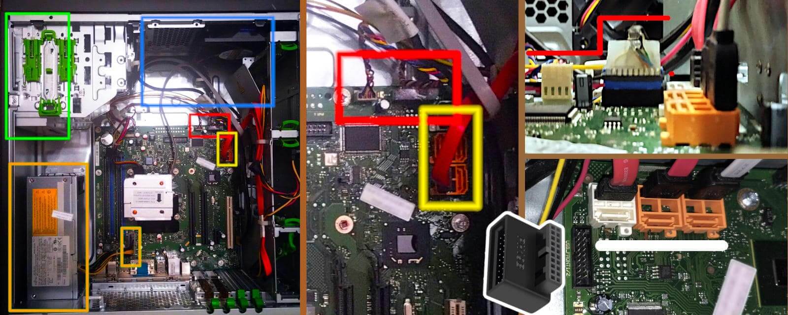
The first problem in installing the Nvidia Tesla K80 into a Fujitsu Esprimo P910 is related to the high of the USB 3.0 male connector which prevents the GPU card to be installed into the only PCI express 3.0 x16 because the one near the CPU is mechanically a x16 long but it is a PCIe 2.0 x4.
right click menu to enlarge the image in a new tab
right click menu to enlarge the image in a new tab
Cooling the K80
The original air-flow splitting is a good way to keep ventilated both the internal of the case and the SATA hard-disk rack that is available at the bottom of the case in three bays. A lot of physical space for installing a lot of data storage units makes this tower PC a good candidate for an advanced NAS for local caching. In fact, within a basic hybrid cloud paradigm, it would collect the daily data of a middle-size office to upload/sync it during the night in order to prevent clogging the internet connection during the working hours. Considering that as high is the working temperature as short the SSD/HDD life average time is, installing many storage units is not a great idea. The best is to dedicate this PC tower for computational purposes and leverage ethernet and USB 3.0 for exchanging data in packets and in large chunks. In fact, on the top of the original hardware configuration, there is also a 225W TDP GPU card and an extra 350W PSU. However, the choice to mount the extra PSU on the highest DVD ROM bay creates a safe distancing between the other two major sources of heat. Moreover, because the extra PSU is at the same level of the original PSU, both PSUs are sucking warm air from the top of the case and pushing it out. Which keeps the CPU and the GPU safer but potentially puts the PSUs at higher risk of overheating due to a potentially lack of fresh air to cool down themselves.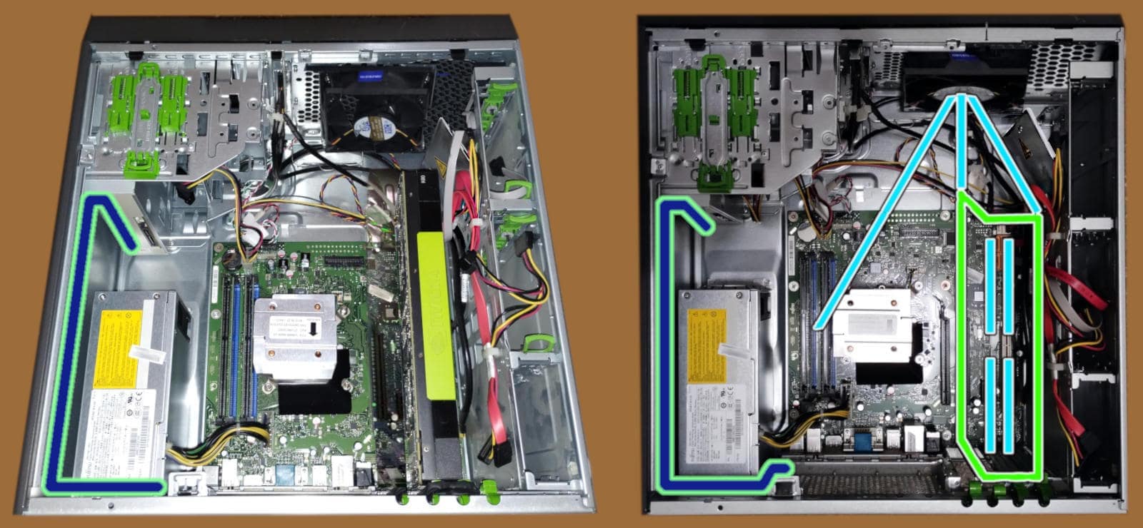
right click menu to enlarge the image in a new tab
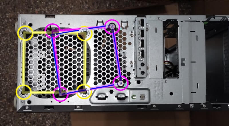
Bricolage for the fan
In order to replace the cooling fan, I decided to use four skewer wood sticks to find the suitable holes to use to fix the fan.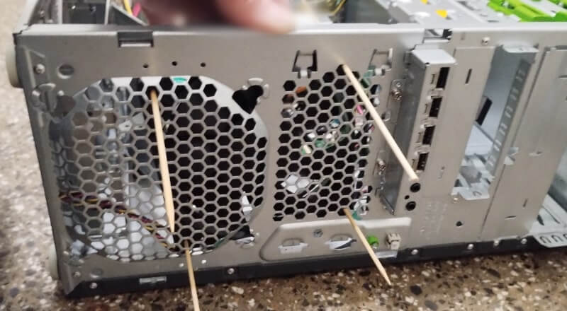
right click menu to enlarge the image in a new tab
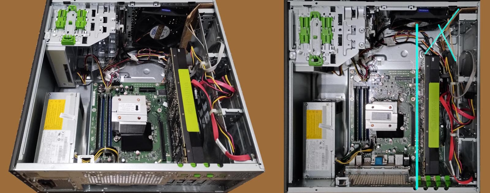
A hands-craft baffle
The new deflector is quite simple: a plane bent at 45° c.a. which pushes on the corner of the case and leans on the passing-by-the-fan wood-stick by a horizontal cut. Another wood-stick is embedded vertically on the bended edge that matches and gets stuck behind the original air-flow deflector. The vertical wood-stick keeps the new deflector steady and rigidly vertical while a 90° bent side pushing against the case corner provides the second steady vertical line.Is that a professional piece of hand-work? Obviously not.
However, it is a pretty good try to start with designing a 3D printable additional air-flow. Until, we consider the cost and the labour related to 3D printing. Including that PLA is more flammable than cardboard and wood-sticks. That it has a higher energy density to sustain a fire. Then, we may agree that once properly covered by insulating silver strong-duct tape, the cardboard deflector would look much more professional.Conclusions
Yet, this dual-PSU configuration has to face the proof of the time but this also depends on the choices I made. Instead, the approach in general seems valid because it does not imply any particular mod that would be forbidden into a common PC shop or PC hardware support center, or reparation. In fact, it is a matter of just assembling some common spare parts and all these parts are available on different e-markets, from different sellers and producers. Making a comparison with the mods that I have seen shared on Reddit and other similar forums - but some are 4 years old - this is a quite simple, comfortable, standard and safe way to go. Despite this, it is not for everyone because assembly or modification of a personal computer hardware configuration requires manual dexterity to use tools, and a little experience.·NOTICE·
Before going for this way presented in the above sections, consider to give a try to the 9cm fan least-effort option presented into "Preparing for installation" section of this manual or here in a related web page. Later, the way presented in the sections above, just in case.
External sources
In the first link there is a practical example using the nvidia-smi command to cap the maximum power consumption in order to prevent overheating problemsShare alike
© 2025, Roberto A. Foglietta <roberto.foglietta@gmail.com>, CC BY-NC-ND 4.0